Showing posts with label English. Show all posts

Thursday, 3 January 2019

Basic Electrical Measurement Devices

Voltmeter
            Voltmeter is an instrument used to measure the potential difference between two points. Voltmeter available in both analog and digital type. AC and DC voltages are measured with different voltmeter, in case of Analog and mode has to be changed, in case of Digital. It should always be connected parallel to the components of which voltage has to be measured. The resistance of a voltmeter must be very high. The standard SI unit for measured voltage is Volt(V).


Ammeter
           Ammeter is an instrument used to measure the current flow through it. It also available in both Analog and Digital. It should always be connected in series with the circuit of which current has to be measured. The resistance of a Ammeter must be very low, The standard SI unit for measured current is Ampere(A).


Ohm meter
               Ohm meter is an instrument used to measure the electrical resistance of a component. It also available in both Analog and Digital. It should always be connected parallel to the component of which resistance has to be calculated. The standard SI unit for measured electrical resistance is Ohm(Ω).


Multi meter
               As the name implies, multi meter is used to measure various electrical values by changing the mode in it. Using a basic multi meter Voltage, Current, Resistance and Continuity of different ranges can be measured.


Series Circuit & Parallel Circuit

Series Circuit

            In series circuit, components are connected end to end in line to form a single path for electron to flow. Hence the current throughout the circuit will be same. If any of the component is disconnected or removed, then circuit becomes open and no current flows in the circuit. The circuit below illustrates the series circuit.

In the above circuit positive is connected to the first component(R1) and negative is connected to the last component(R3). Since all the three components are connected in series, current through all the components are same. But voltage across each components varies.

In the below image the component R2 is removed, so the circuit becomes open and there is no current flow in it.


Parallel Circuit

               In parallel circuit, components are connected across each other like a branch. It makes many path for electrons to flow but voltage across all the branches are same. Even if any of the component is removed, the current through the other components continues to flow.

In the above circuit all the components are connected across each other, which makes several nodes. The positive supply is commonly connected to all the components and negative supply also commonly connected to all the components. Here each components makes individual closed circuit, so current flow through each component varies.

In below image even if the component R2 is removed, the other components remains closed and current continues to flow.


Things To Remember

Series Circuit
1. Current throughout the circuit same
2. Voltage across each component varies
3. If any of the component is removed, then no current flows in the circuit.

Parallel Circuit
1. Voltage across each components are same.
2. Current through each component varies.
3. Even if any of the components is removed, current continues to flow to the other components.

Wednesday, 26 April 2017

Short overview of Current

What is meant by Current??
        
                 If electrons moves in a conductor, we say current flows in it. For such electron movement voltage is needed. To create a voltage, potential difference is needed at the two points of conductor. Which means if potential at one end of the conductor is higher or lower than the potential at other end of the conductor, Voltage is created so that current flows.
         To understand the current flow direction, let us seen an example...
   Electrons flows from higher potential to lower potential    (Or)  Electrons flows from higher density to the lower density.
    In the above Picture, 1 has higher potential and 2 has lower potential than 1. So a potential difference is created between two points of conductor. This creates a voltage and electrons flow from high potential 1 to the low potential 2. So current also flows from 1 to 2.
Note: Potential difference and Voltage are more or less same.


  In the above Picture, 2 has higher potential and 1 has lower potential than 2. So a potential difference is created between two points of conductor. Due to this potential difference electrons flow from high potential 2 to the low potential 1. So current also flows from 2 to 1.


Types of Current:
                           1) Alternating current-AC
                           2) Direct current- Dc

Alternating Current:
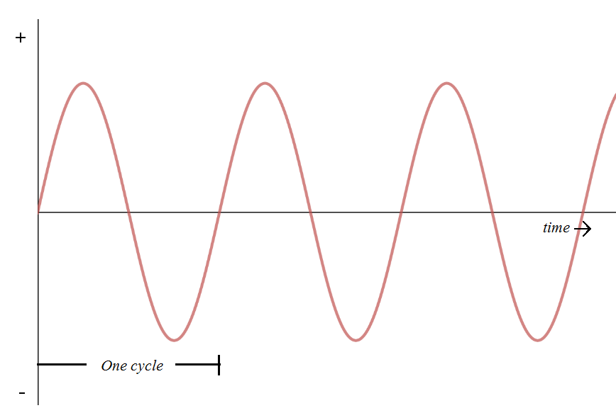
                     As the name implies this type of current often alters between positive and negative. The number of time it alters per second is called frequency.
    Alternator helps to produce alternating current.

Direct current:            
                 As the name implies this type of current always flow directly either in positive or negative, it doesn't alters.
     To produce Direct current, Battery, solar panel, some chemical reactions, thermo electric current, and numerous methods used.

Monday, 17 April 2017

Some Important Laws of Electrical

The generator which is helpful in generating electric current and electric motor which is utilizing that generated current, both plays a vital role in electrical. Magnetic field is necessary for the working of both of these machines.


FARADAY'S LAW :
          Faraday's law of induction is the fundamental of Electromagnetism. It is the basic operating principle of Transformers, Inductors, Generators and Electric motors
   Faraday's law states that, if the magnetic field around a coils of wire changes, an EMF will be induced in it.
Whatever may be the reason for change in magnetic field, EMF will be induced.

How a magnetic field can be changed?
    
            1. By changing the strength of magnetic field.

            2. By moving a magnet towards or away from the coil.

            3. By moving the coil into or out of the magnetic field.
            4. By rotating the coil relative to the magnet.

            5. By rotating the magnet around the coil.


To understand this law through video visit : https://youtu.be/wCXCpc3BBcM


FLEMING'S RULE : 
             
                     This rule describes about the direction of current, magnetic field and force or movement when a coil or conductor is placed in the magnetic field. It is classified in to two namely,
            1.Fleming's Left Hand Rule
            2.Fleming's Right Hand Rule

Fleming's Left Hand Rule :
                      Fleming's left hand rule is used for the Electric motor application. When a current carrying conductor is placed in a magnetic field, a force will be induced on the conductor in such a direction that perpendicular to the direction of both magnetic field and current flow.
    According to Fleming's left hand rule, Thumb finger, Fore finger and Middle finger are stretched perpendicular to each other, in such case thumb finger represents the direction of force or movement, Fore finger represents the direction of magnetic field and the Middle finger represents the direction of current flow.

Fleming's Right Hand Rule :
                    Fleming's right hand rule is used for the Generator application. When a conductor placed in a magnetic field is forced to move, an EMF will be induced in it, if a closed path is provided currents starts to flow.
         According to Fleming's right hand rule, Thumb finger, Fore finger and Middle finger are stretched perpendicular to each other, in suc
h case Thumb finger represents the direction of movement, Fore finger represents the direction of magnetic field and the Middle finger represents the direction of induced current.


OHM'S LAW :
       
             This law states that current flowing in a conductor is directly proportional to the voltage applied to it and inversely proportional to the resistance.


Important Notes :
  •             Electrons or charge carriers moving in a conductor is denoted as current flow.
  •             The amount of current is dependent on the amount of electrons moving.
  •             The voltage applied to conductor decides the amount of electron flow.
  •             In every conductor to resist the flow of electron, some resistance will exists in itself. The amount of resistance differs by the length, area and material type of conductor.
  •             If a current flows in a conductor, magnetic filed will be created around the conductor. So to create a magnetic field magnet is not necessary, passing current in a conductor itself create a magnetic filed.
  •                                     

         Symbol         Unit
    Voltage           V    Voltage(V)
    Current            I   Ampere(A)
    Resistance            R   Ohm(Ω)

Basic Electrical Measurement Devices

Voltmeter             Voltmeter is an instrument used to measure the potential difference between two points. Voltmeter available in both ...